
The HP3455A is a great device - Old, but great. It is a precision multimeter (voltage, resistance), made by HP in the 1980's.
For part 2 (logic and control) CLICK HERE.
For part 3 (analog and black magic) CLICK HERE.
It's a 6 ½ digit beast, with some fun features, a little math, some intelligence. It was a real beast in it's day, connectable to other fun equipment. It sold for around 3000 USD in its time, which is about ten bazillion of today's money. Or some such. The datasheet and manual are available for download:
[wpdm_file id=12] [wpdm_file id=13]
(WARNING: Really big file!)
The service manual's an impressive piece of reading - at over 200 pages it provides details on the theory of operation, schematics, details on all of the parts... Not the crap you get today.
I bought it for a fraction of that price, and now I'm the proud and happy owner of a fine piece of equipment. I decided to do a peek inside - not a real teardown, just a peek 🙂
This is part 1 of the teardown. The gallery at the bottom contains all of the images for this part. The more interesting ones are posted with extra commentary.
NOTE:
No electronics were harmed during this teardown. Precautions were taken to avoid ESD and the other popular ways to kill stuff. After reassembly the meter is working just as well as it did before. I did cut my finger though.
The Big Picture
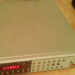
The whole meter in all its glory:
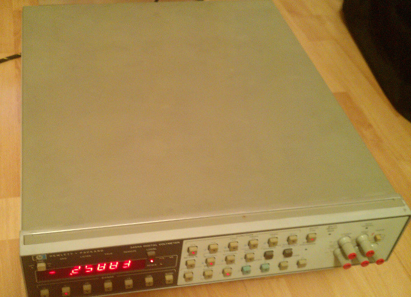
The Beast - a total view
And the backside:
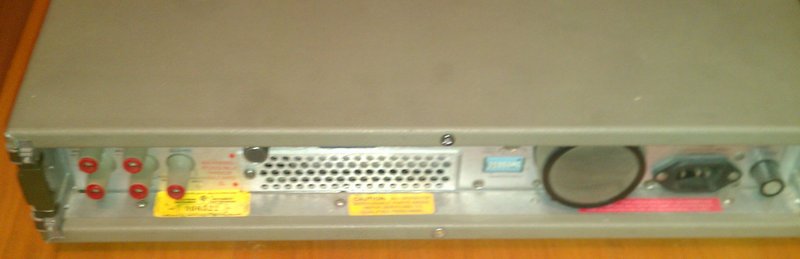
Multimeter backside
It's a really big device - desktop... or rather bench top. Weighing almost 10 kg and being over 420 x 520 x 80 mm (W x D x H), this isn't meant to be portable. Although they DID include a great little handle - a LOT of attention to detail went into this bugger.
The Front Panel
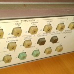
The front panel is well lit. The current meter configuration is indicated by the lighting up of the button with the function as seen in the picture below. The function and setup can be changed by pressing the required button.
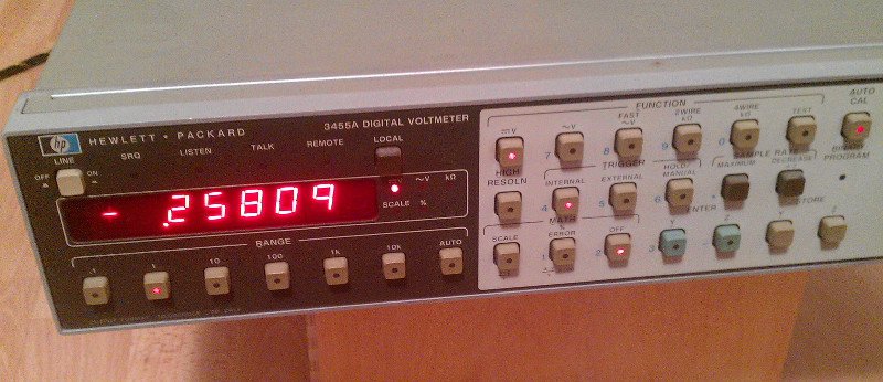
A happy working meter
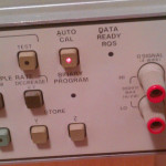
The front measurement terminals are exactly what you'd expect - 4 terminals for 4 wire resistor measurement, 2 wire measurement and voltage measurement. There's also a guard swtich/terminal.

Front panel - input terminals
There's a lot of communication LEDs/indicators. The buttons allow you to select and set various functions - the integrated math, storage, sample rate, trigger, measurement type and similar. All in all a very user friendly and straight forward machine.
The Backside
There's nothing really special about the back side - it has what you'd expect from a device like this.

Power, fuse and fan shot
The mains input, fuse and voltage selector, the fan cover and the bus setting. And a trigger.
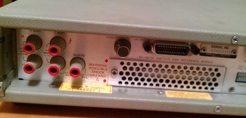
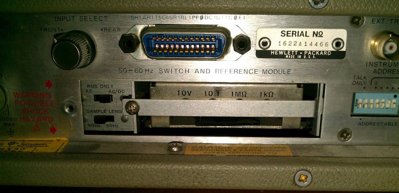
More snaps of the backside and the cal module cage
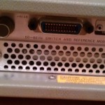
The other side of it holds the backside measurement inputs - for fixed measurements, rack systems and such, the switch that selects between the front and back inputs and the cage door for the calibrations module. Also there's the serial number and an obscure bus interface. It also tells us that there are no user serviceable parts inside - pitty 🙁
The calibrations module
This module pretty much defines how accurate the whole system is - it holds the voltage reference and the resistance reference. It can be removed - the manual describes advises that you can interchange these modules between systems and it is practical really - you can send your calibration module to the lab and keep the device running. Practical really.
Calibration module - slightly opened
The module can be adjusted slightly by these trimpots. There's a whole procedure documented in the manual. Note the pull ring - they've really gone into a lot of trouble and attention to detail - when this module needs to be pulled, they actually included a small, rotable plastic pull ring, that enables easy removal of the module:
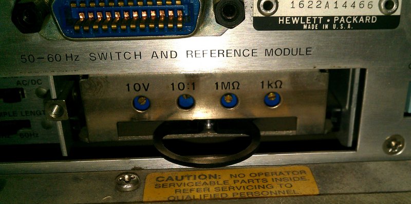
Calibration module pull ring
The module itself is a small metal box of seemingly no interest:
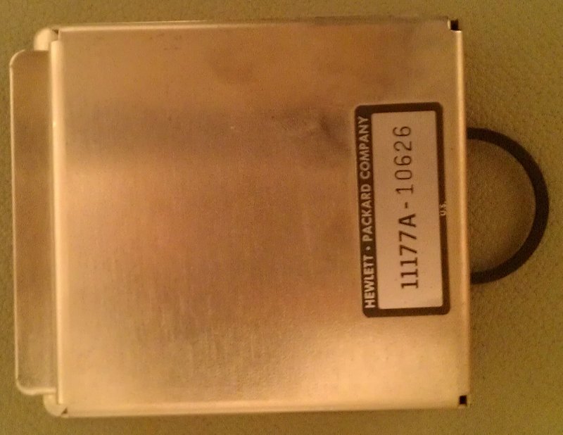
The calibration module - a nice metal box 🙂
Industrial strength boring. But what's inside:
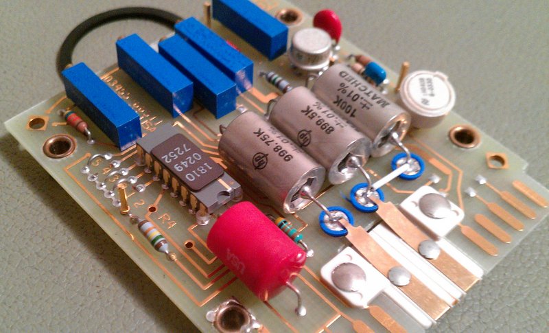
Calibration module detail 2
Precise and fun stuff. Matched HP precision resistors of +/- .01% in a gargantuan metal can. An HP ASIC. A big red resistor? And the voltage reference: Something. But it's probably a rebranded LM399 - a lot of precision meters have this IC as was shown on various teardowns. Also, the board is heavily gold plated. Note the standoffs on the ASIC...
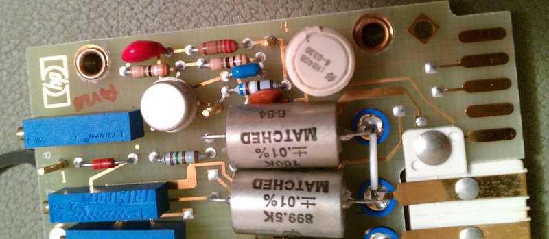
Calibration module detail 1
The connoisseur will note the high impedance standoffs for the resistor reference - a special plastic stand that isolates the high impedance stuff (ends of the resistors) from the rest of the board. These are then connected via flying cables with the rest of the circuit. Also note that the resistance reference was connected to the rest of the system not like the voltage - on the board - but rather through a special plastic connector so that no gunk or crap may cause leakage and measurement errors. They were pretty serious about this stuff.
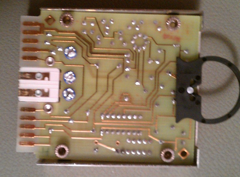
You can see these islands on the bottom of the board as well as a guard ring:
The module plugs into the rest of the system through a simple, but high quality connector:
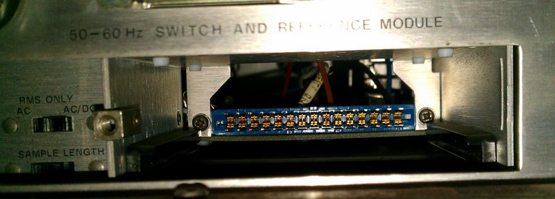
Calibration module connector
And that's it for now. Check back later for more peeks inside of this fun device!
Also, there's a few shots here and they are in better resolution in this gallery:
-
- The Beast – a total view
-
- Front panel – buttons
-

- Front panel – LED display
-

- Front panel – turned on
-
- Front panel – input terminals
-

- A happy working meter
-

- Multimeter backside
-

- Backside terminals
-

- Another snap of the terminals and the cal module fixture
-

- More snaps of the backside and the cal module cage
-

- Power, fuse and fan shot
-
- Calibration module cage
-

- Calibration module – slightly opened

-

- Calibration module – trimmers
-

- Calibration module pull ring
-

- Detail of the calibration module
-

- The calibration module – a nice metal box 🙂
-

- Calibration module connector
-

- The Bottom
-

- The calibration module PCB – bottom
-

- Calibration module PCB – top
-

- Another snap of the calibration module PCB
-

- Calibration module detail 1
-

- Calibration module detail 2
-

- Calibration module detail 3
-

- Calibration module connector
-

- Connector detail

4 Responses to HP3455A teardown - part 1 - calibration module and the backside