
I love going to the flea market - you find all sorts of fun stuff, bargains, trash and the occasional treasure that is being sold for next to nothing. This posts fits into the 'fun stuff' area - while at a flea market here in Bratislava I stumbled upon this scale, being sold as broken, for 3 EUR. I bought it, assuming that the worst case scenario would be that I get a tensometric bridge, some fun analog stuff and perhaps a graphical display. Best case scenario: I get a serious digital scale for peanuts.
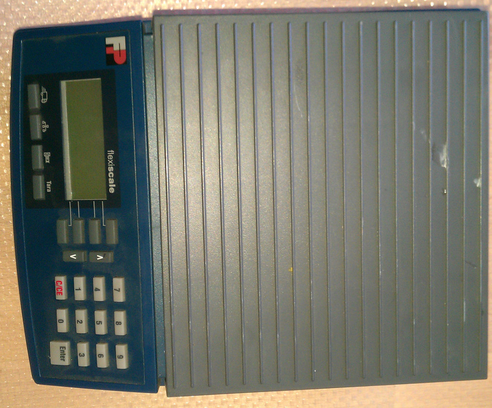
Scale - top view
The scale is made by the FRANCOTYP-POSTALIA mailing solutions company, which seems to be a company specializing in this sort of stuff - they have a pretty impressive line up. Depending on the specific model, this scale can weigh up to 13kg (30 lbs). According to the manual, it offers quite a lot of options for mailing, determining mail pricing, it can connect to all sorts of machines.
Initial impression
The device is pretty sturdy - it has to be to withstand postal postal office workers. The whole system is housed in a plastic enclosure and is pretty heavy. There are 4 adjustable legs on the bottom side of the device, with which you can adjust the angle of the scale - ideally it is completely horizontal - a small bubble level under the weighing board can help you with this setup.
Plugging in the power confirmed that the device does not work - it did not power up, did nothing useful - as such I have to assume that it is indeed not working.
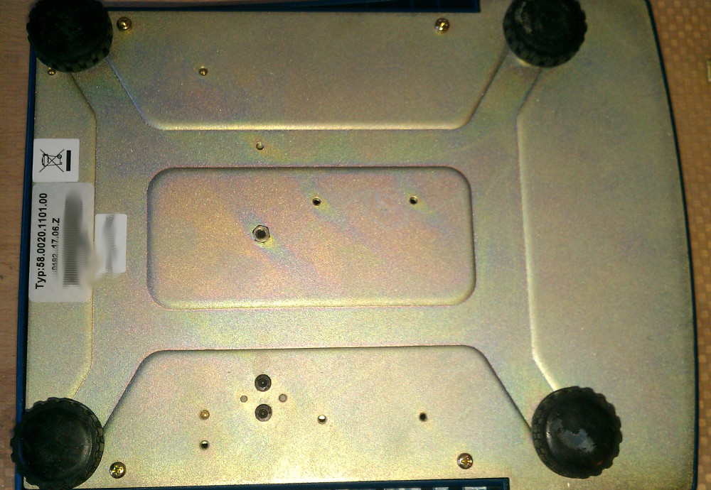
Bottom view
Bubble level
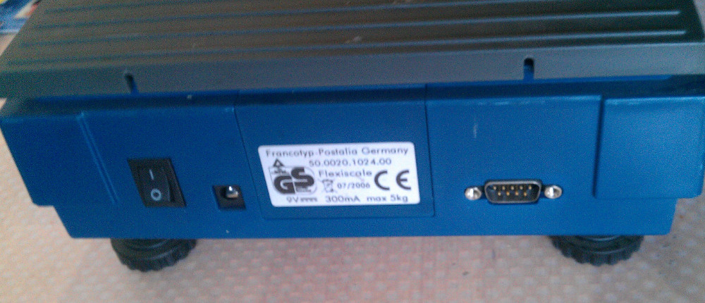
Back view
The device has an RS232 interface, which can be connected to a PC or all sorts of obscure mailing equipment. It is powered by 9V DC @ 300mA, by an external adapter.
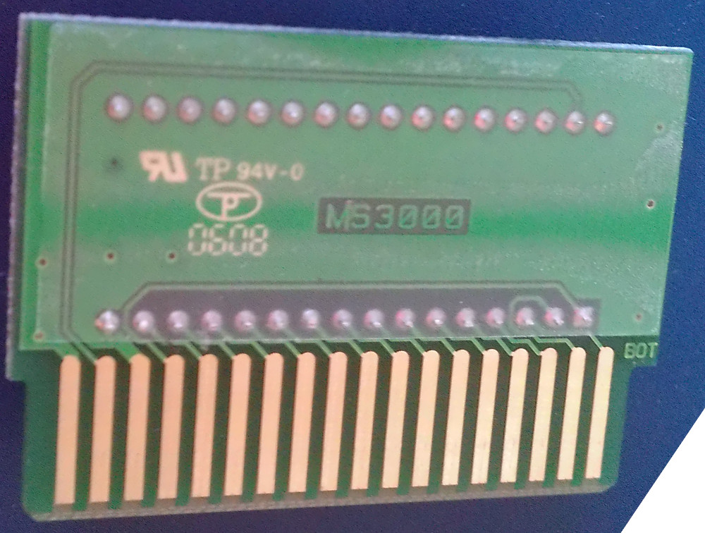
Now this is where it gets interesting - note the area between the power connector and the interface connector - there's something there! A calibration module? Additional slots for extra functionality? The Meaning of Life?

Rate module
None of the above actually - this is a "Rate card" - according to the manual, this EPROM contains the rates as well as all of the business logic that determines how much are you going to pay for a letter, when shipped via the overnight super special saver from Elbonia to Kneebonia. This is horrible - does this mean a minor change in pricing policy will force thousands of boards like this to be shipped out all over the country? Seriously? It's an EPROM, as such it can't be updated without erasing it. In theory some kind of unholy patch system could be used - you start of with a 1% filled memory, the rest erased, then as changes come you fill the next page and work from there, always looking at the latest page. The manual says you can update rates by either a new card or via modem - you connect the device up to a modem, navigate through a menu and it just downloads the newest rate logic. Into the EPROM for some reason... Wouldn't FLASH have worked better? It was 2006! They actually use a FLASH memory inside of the device for firmware! Which is not going to change half as often... a small serial FLASH would have done the trick... oh well, who am I to judge.

The Keeper of the Rates
Decoupling? We don't need no stinkin' decoupling
The complicated PCB
Opening up
Upon opening the device up we are greeted with the following:
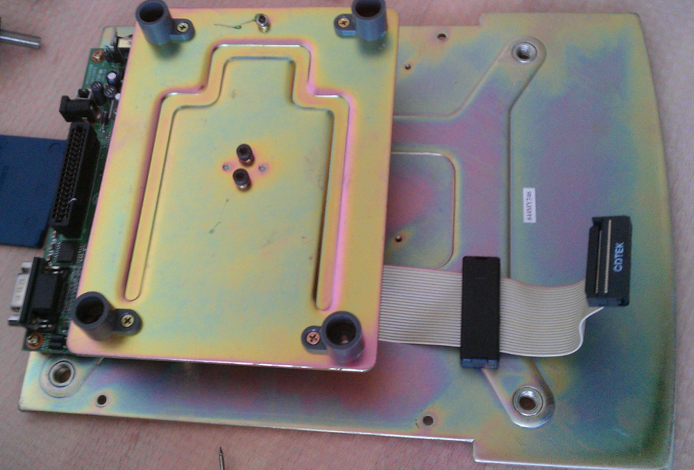
Whole view - inside
This is a pretty typical setup for a scale of this type - a plate whose weight is measured is connected to a load cell, on which a tensometric strain gauge rests.
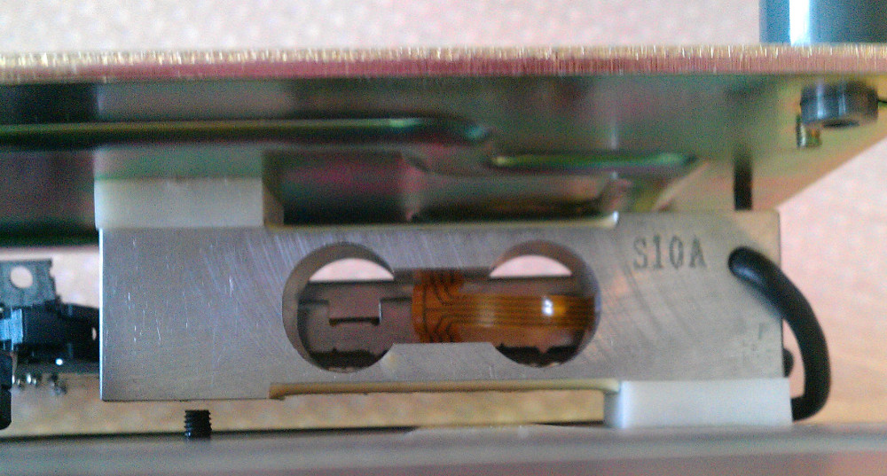
The Heart
The load cell and the strain gauge are literally the heart of the scale - you could throw away the electronics inside and use this with a (very) good multimeter and power supply as a scale (although horribly impractical obviously). A strain gauge is essentially a resistor, that you can stretch, which will cause it to change its resistance - by a VERY small amount, they are generally connected into a bridge configuration. A load cell is a machined piece of metal that deforms in a controlled manner when you apply a force onto it.
But getting a good signal out of a strain gauge (even in a bridge configuration) is not simple - the whole range of a scale can be hidden inside a few milivolts - the gauge is a voltage output bridge, with a very low signal on the output. You can get, say, 1mV/kg of a total range of 0-5kg - obviously depending there are hundreds of types out there. But you can see the problem - if you wanted a 0-5kg scale with a resolution of 1g you have to have an ADC resolution of 1 microvolts. You can amplify the voltage obviously, but amplifying small DC signals is a special kind of pain to get right - at microvolt levels thermal voltages start creating offsets and you get to explore all the fun imperfections and errors of operational amplifiers. Chopper amplifiers are used for stuff like this. Suffice to say it's not trivial. There are lots of app notes from many companies with great advice on how to do stuff like this properly.
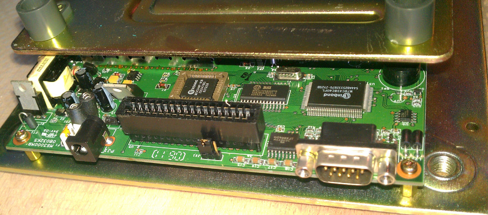
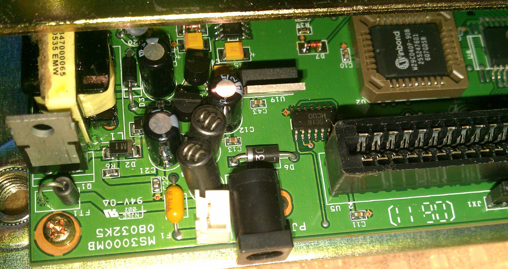
The electronics
The control electronics are all placed on a single board - this contains the power supply, all of the processing, memories (aside from the Rate Card), interface and the ADC and analog front end. Also, there's an unlabeled jumper! How exciting!
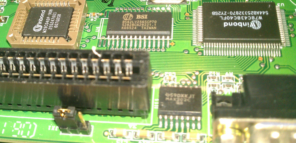
Electronics - detail
The processing part seems to be pretty simple - a W78C438C40 processor (according to the Internets it's a 8051 clone without any program memory (uses external, probably the 29C040 FLASH memory) and a 62LV256 SRAM - a simple setup, as generic as they get I guess. There's a MAX232 variation doing the RS232 interface on the bottom of the board.
RTC and supercap and misc view
There's an RTC in the device to allow the device to retain time - pretty useful in a post office I guess. The RTC is backed up by a supercap. Hopefully the calibration constants are stored in a non-volatile memory. There's a small serial EEPROM on the board, I believe they are stored here. On the far side of the board you can see the display and keypad connector.
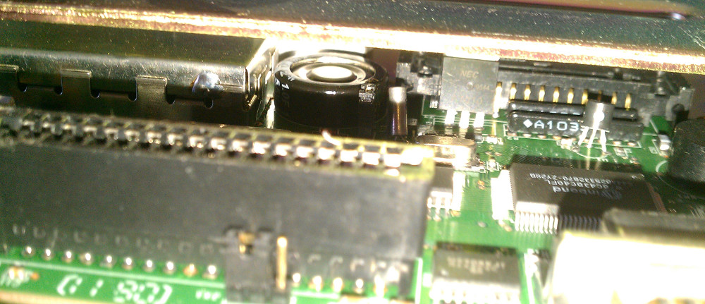
The analog part and strain gauge connection
Now, this is the analog part - unfortunately it is inaccessible due to it being shielded - I hope the problem is not there, but it does not seem like it. If the problem is there, I will open it, but I am hoping to avoid this. The shield of the strain gauge cable connects to the chassis. The strain gauge cable is soldered onto the board. It's pretty close to the power supply transformer (I'm guessing it's a transformer, not a choke).
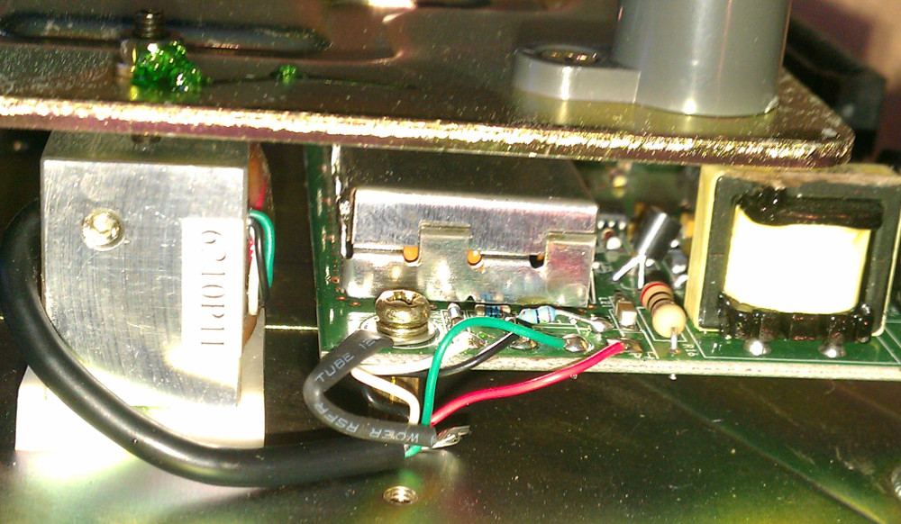
Power supply region
The power supply region - some filtering, some protection, some step down conversion. Nothing visibly burned. The transformer is probably there to create some negative supply voltages that analog stuff often needs. Or it's just a common mode choke. Dunno. At a rough glance the path from the main power connector goes through the main supply switch (small white connector), then onto a fuse (which is not changeable, because reasons), then off to some filtering and I'm guessing that one of the diodes there is in series to prevent reverse polarization.
To summarize: A bog standard 8051 control system looks into an ADC, that has an analog front end that takes and amplifies the signal from the strain gauge. The resulting data is fed into some logic that determines how much you pay for your mail and displays this info on a display. The whole system is powered by a power supply. When power is applied, there is no reaction. There is no visible fault or problem that would stand out.
Repair
When repairing stuff most of the time you have these kinds faults (sorted-ish by order of seriousness):
- No fault at all - this is the best case - occasionally something is reported as broken, when it is in perfect working order, only the user can't use it, it is obsolete, someone has fumbled some setting... that sort thing. Or it can have scratches, dents, visual faults - nothing that would impede core functionality.
- Power supply - this can be both great and both horrible, depending on the situation. It's great when there's a trivial SINGLE fault - a blown fuse, a burned PCB trace, a burned voltage regulator, a croaked resistor, an leaked/exploded cap... simple, visible things. Most of the time you can easily replace them with similar off the shelf components. Basically, when a power supply part dies you hope that it died in a way that disconnected the rest of the electronics inside. Generally it can be fixed pretty easily. It is worthwhile to investigate if it is the problem or just a symptom though - if something further down the line has croaked and shorted the power supply, which burned down, or blown a fuse, things can get messy.
- A dead part/port - occasionally a part just croaks. Replacing it with the same or very similar will solve the problem. Finding the part in question can be anywhere between "find the source of the smoke and hellfire" to "a few hours of poking probes onto various pins". Random part deaths can stem from several sources. The simplest one is old age - electrolytic caps are particularly known for this. Another source is ESD damage, or just damage from misuse where only one or a few parts get hit - someone puts 24VAC onto your pampered little high impedance +/- 2.5V input, your op amp preamplifier nobly sacrifices itself before the protections kick in, so that the rest of the signal path may live.
- Calibration memory/firmware memory fail - occasionally memory chips just die, or lose bits - by old age, by misuse, or, if someone was particularly nasty, he could have stored the calibration constants for your exceptionally pricey instrument in a volatile memory - such as a SRAM backed up by a battery. Now, 20 years later, someone comes to you and asks what does "CAL MEM ERR" mean (yes, HP 3458A, I do mean you...)... If it's just firmware it's pretty easy - memory images for most of the popular stuff (old meters, etc.) are available on the net. Or you could talk to the manufacturer, or cannibalize similar units, or copy one from a working unit. When a calibration memory fails, that's worse - you can't just copy that of another instrument obviously as the whole point of calibration constants is that they are unique to your system. Ideally, one would have these memories backed up, but that's not exactly common. As such, you're gonna have to get it calibrated or calibrate it yourself. Which can cost a pretty penny.
- The horrible starts when a power supply dies in such a way that full mains voltage, or the full input voltage is allowed to pass down the line - imagine if you have a +12V input, you are running your logic at +3V3 and suddenly your regulator dies in a manner that shorts the +12V and the +3V3 rail. Suddenly, your nice, low power microcontroller and your sensitive analog block that you have pampered with all sorts of filtration and love is getting the full Monty. Faults like this can generally be easily seen as this causes widespread mayhem - blown chips, blown lids, blown parts... current starts traveling in ways that it was not meant to travel. A similar situation can be present when some part that is on both regions dies and connects two parts of a system that are meant to stay separated - like an H bridge which connects to both the control logic rail (+3V3) and to the power rail (+12V). Assume sparks. Repairing this kind of damage can range from replacing a single part to replacing a whole region. Or even throwing out the whole board as damage that might not be detectable, but will surface eventually might have occurred, or replacing most of the board is simply not worth your time and money. If you can even get the chips. This kind of damage can occur not only by means of your internal power supply, but by means of external sources - some user manages to plug +12V into your microphone input jack, someone assumes that an input range of +/-2.5V means 24VAC is OK, etc. Bonus points for lightning damage.
- The sensor/obscure part/expensive part/irreplaceable part dies - this is the amongst the worst. There are devices that have extra special parts that is the very heart of it, are as obscure and specific as possible, have no off the shelf replacement and when they die, the only other source of the part is to cannibalize a unit that has a working part, or buy the replacement part, which might not be available or might cost almost as much as a new unit. Examples of this include tubes, lamps, ASIC sensors, sensor assemblies, precision motors and drives, mechanics, optics, lasers... when such a thing happens there's a good chance you're buggered, it's beyond economic repair, or it'll cost a pretty penny or quite a bit of luck.
- Utter destruction - the devices is broken. Not just broken as in "does not work", but physically destroyed, cut wires are hanging out, screens are broken, a board is burned over 80% of its surface, or missing all together... such an instrument is beyond economical repair, as it would mean pretty much replacing everything. It can be a source for spare parts, provided you are reasonably sure that those parts aren't damaged - note that the damage might not be visible or even measurable - at the moment. However, the part may have a severely reduced life time. All in all, unless this is Nikola's Tesla very own most prized meter you should just forget about it.
The actual repair
The actual repair was embarrassingly simple - the power switch was damaged in such a way that it made no contact regardless of the position it was in. It retrospect I should have first repaired the device and then started writing the pointlessly long post 🙂
A quick replacement of the switch with something similar enough, and I got a working scale. A check with a few known weights showed that it was working well and was accurate.
So, thanks for reading till this point.