
The analog part is the real heart of the device - here all of the precision magic and measurement happens.
If you are interested in the detailed inner workings of the system, please read the service manual, which is available for download in the first part of this teardown HERE. For the second part of the teardown, click HERE.
The Cover
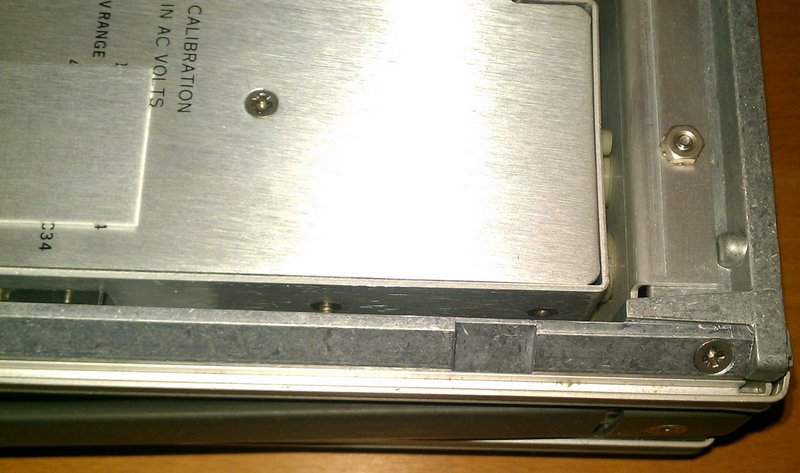
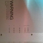
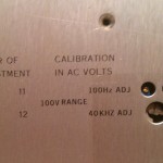
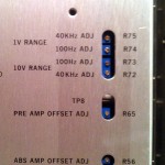
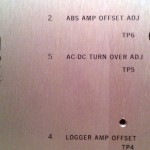
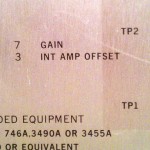
You know you're dealing with something serious from the moment you look at the cover:
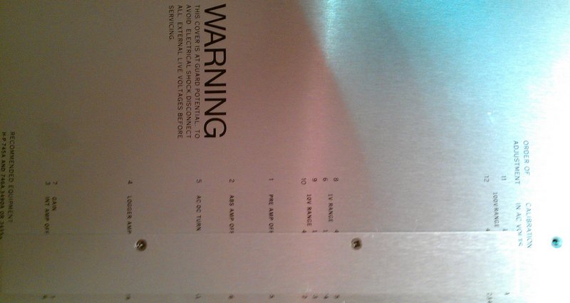
The cover for the whole analog part
The warning is standard enough, what's impressive is the printed out Order of Adjustment and meaning of every individual trim point. There's quite a lot of them - 12. There are also test points.
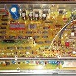
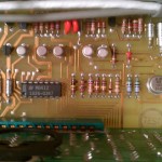
Removing the cover gives us a nice view of the whole analog system:
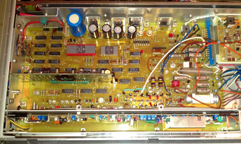
Cover removed
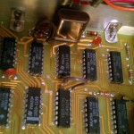
It's a big piece of board and block, with 3 modules on connected to it (not counting the reference). There's some shielding for the extra sensitive parts. There's a connection to the power supply and the logic board. The calibration module also connects into this board.
The analog part is optically isolated from the digital part through optocouplers, which are extra shielded.
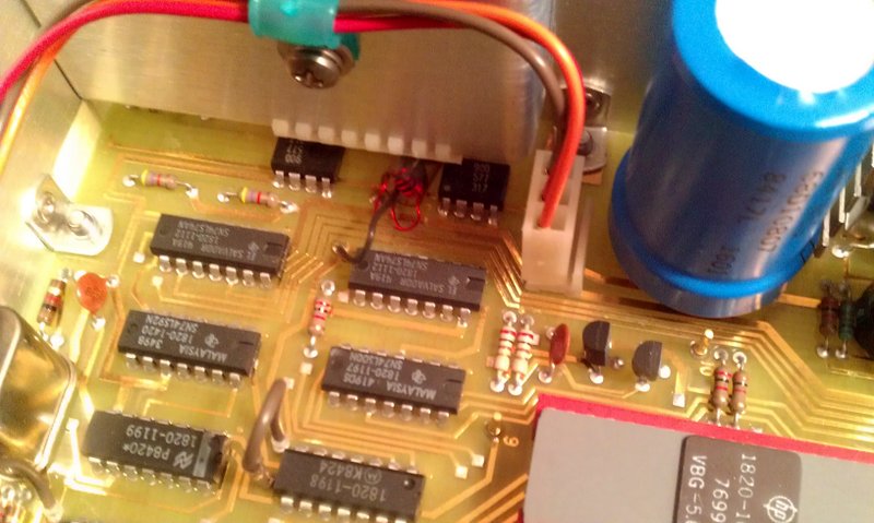
Main module communication
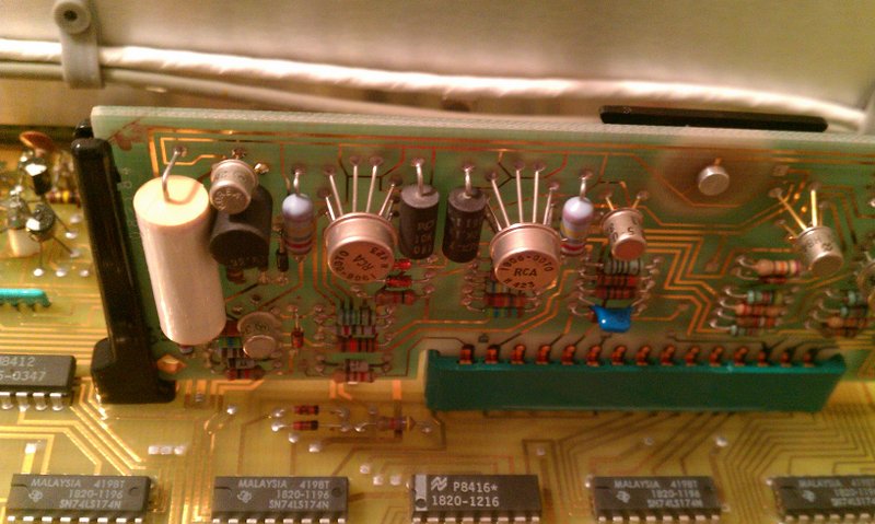
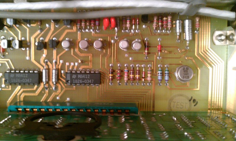
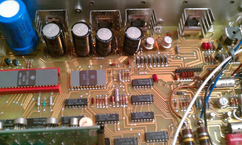
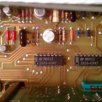
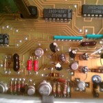
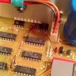
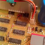
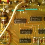
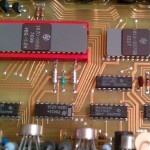
After that, it's the processor and its friend, the ROM memory:
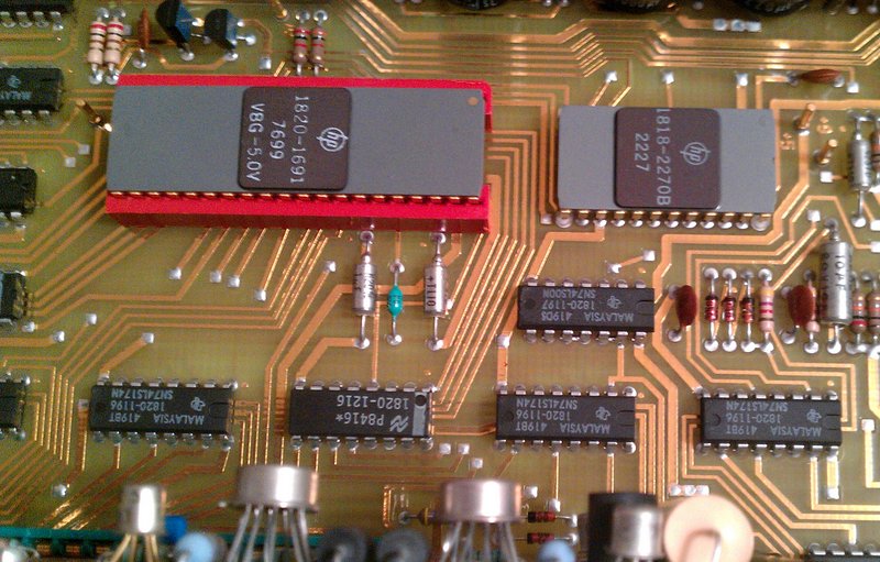
Local CPU and control logic
There's no discrete ADC as such - it's all made out of individual parts - transistors, op amps, resistors, caps and a pinch of black magic. A lot of amplification is accomplished by transistor blocks, rather than op amps. For details on how the whole thing works, see the service manual, section Theory of Operation. It's really interesting reading. The processor does the controlling of the conversion process and reports to the logic board.
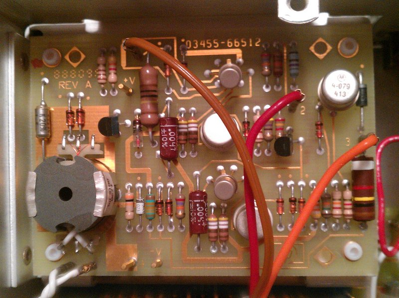
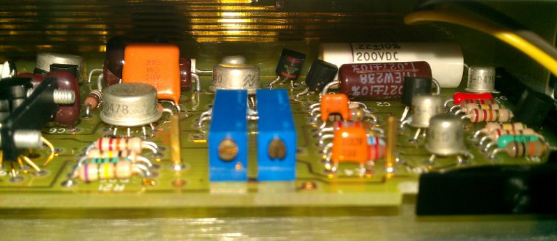
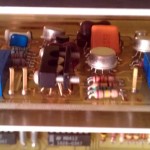
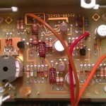
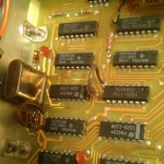
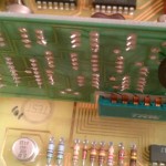
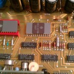
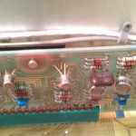
The AD convertor is of multi slope integration design. The heart of the ADC is this small module:
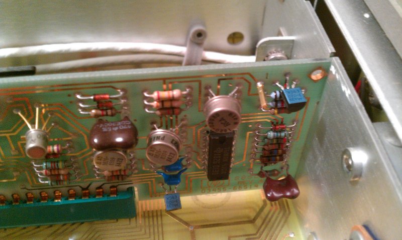
Precission analog board
Precission analog board
On the left is the integration cap, on the right there's a whole bunch of miscellany and very important. The ADC is just the final stage - the signal for it is gained through a lot of conversion, amplification, attenuation and stuff. For detailed info on how it works, see the service manual.
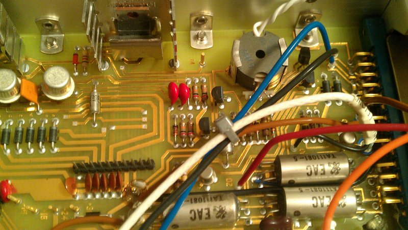
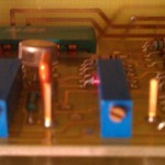
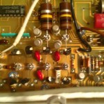
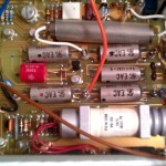
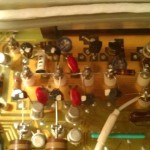
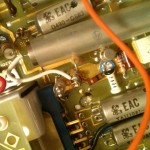
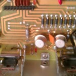
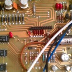
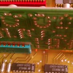
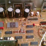
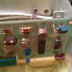
One of the more interesting things is the attenuator - precise little relays clicking and changing the range as needed all of the time.
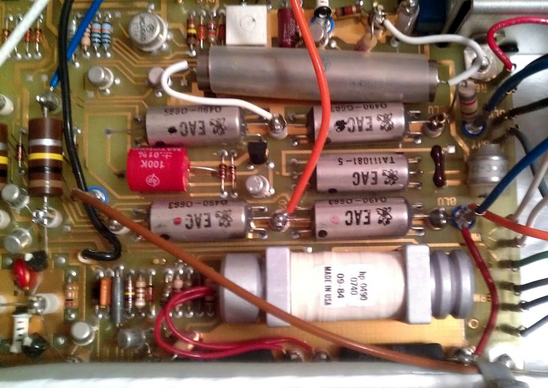
Attenuator and range selector
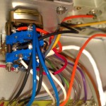
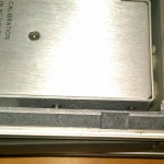
They also switch between various blocks - the resistance convertor, the AC conversion electronics, the voltage input. Note all of the guard rings around the individual relay pins - not so visible here, but more visible here:
Calibration module input switch
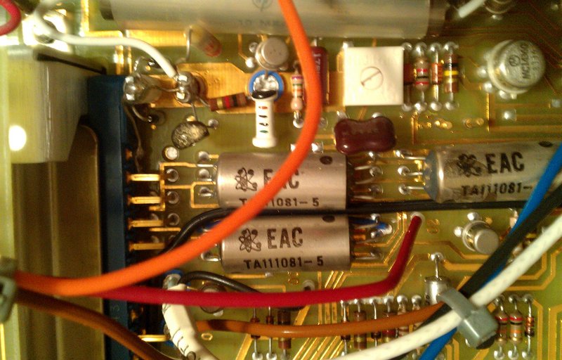
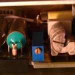
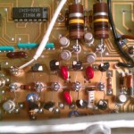
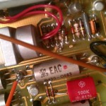
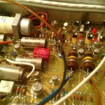
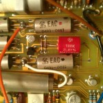
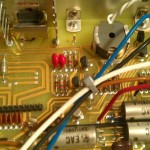
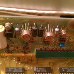
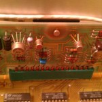
This area deals with the high impedance signals from the reference, ohms converter and gods know what else.
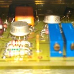
If you've seen the calibration module's special standoffs for the high impedance designed to avoid leakage, you'll just love this region:
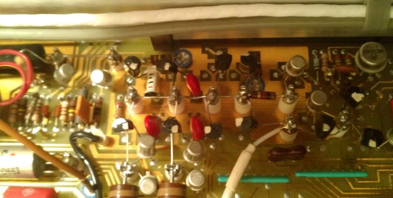
Really high impedance measurement shot 4
Yup! It's all flying on little posts that remove any trace and chance of leakage. Guard rings all around the place, hand soldered, probably matched transistors and who knows what other stuff went into this.
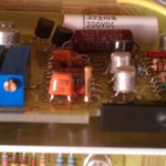
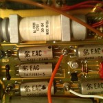
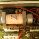
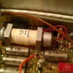
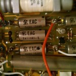
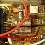
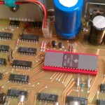
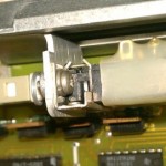
Special, bizzare relay
To top off the high impedance stuff is this special relay that looks like a pipebomb. Yes, that is indeed a relay (K1 in the manual) and it's apparently a special high impedance custom HP relay. Probably hand woven by a greybearded guru or something as well. And another trim point.
There are other interesting things here as well:
An isolated module
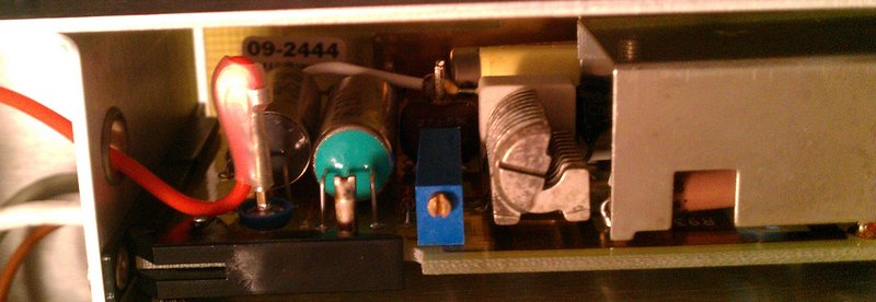
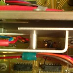
The ohms converter has a floating power supply and takes care of the resistance measurement.
The isolated module power
This is how it's powered - a driven transformer on the power transmitting side, another on the other side.
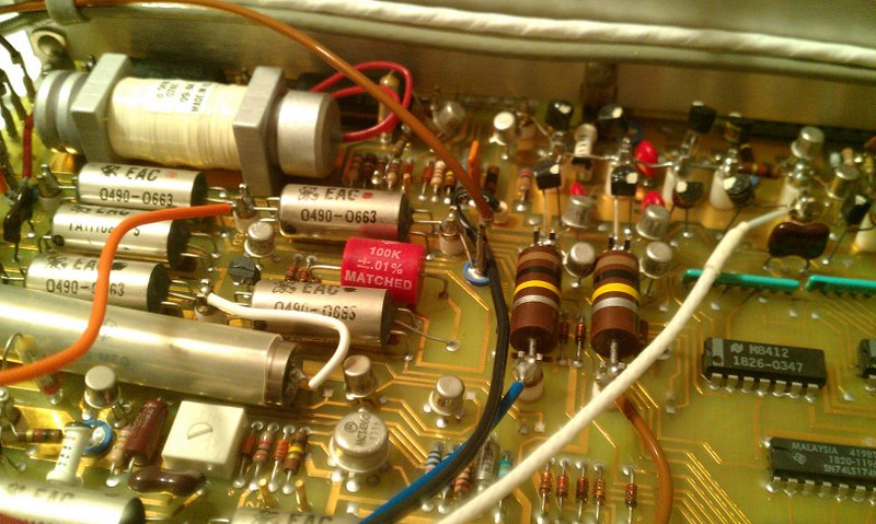
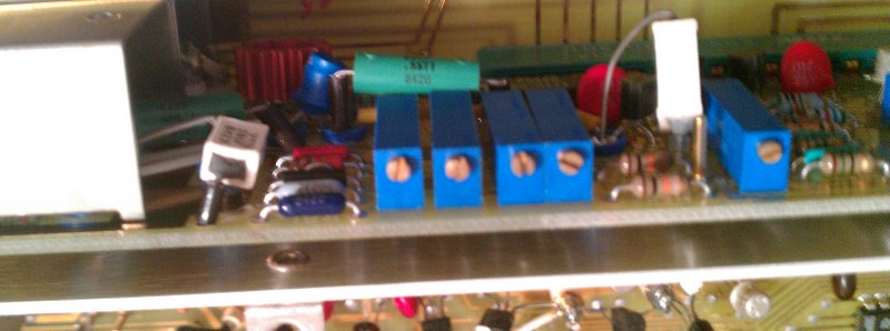
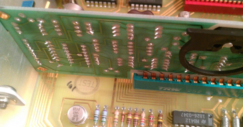
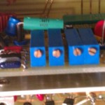
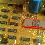
Then there's the True RMS converter board. That one was a little hard to shoot, so it's in many fragments. It's mixed with some other stuff. Generally speaking, the system is a little mixed - there are few regions of the board dedicated to just ONE function.
RMS converter trimpots... the first of many
Input/cal cal/amp board shot 4
Input/cal cal/amp board shot 5
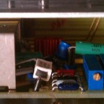
That's pretty much it for the beautiful stuff here. The rest is just logic of general function, some random analog block/part, or something of obscure, yet brilliant purpose. Like this region:
Analog main board shot 1
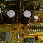
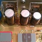
There's also the analog part power supply, heavily filtered.
Power supply
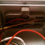
An important, but boring feature is the front/rear input terminal switch:
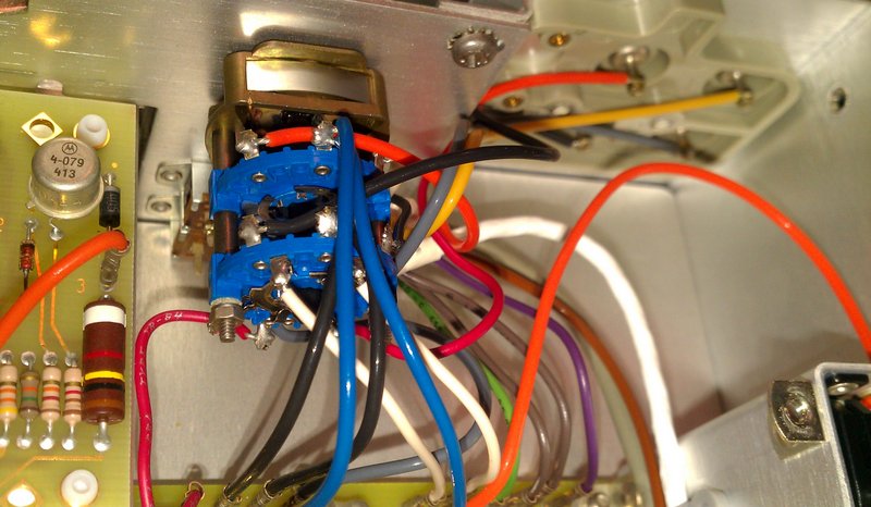
Front/rear input switch
No doubt it is a switch of good quality, but a boring switch 🙂
The rest
This instrument is a great piece of engineering. As far as I can tell they got everything right for that era and shared no expense. Mechanically, it's really impressive - the pull rings on the boards that will most likely never be touched. Ever:
Pull ring for a board
The serviceability of this machine was really good - the manual lists generic replacement parts where applicable - there's a lot of those, most of them, aside from the really obscure HP parts, such as the processor, the mask ROMs and some ASICs. And the monster relay ofcourse.
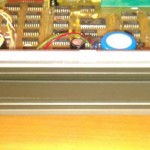
The chassis itself is a massive alluminum alloy cast beauty:
Beautiful cast case
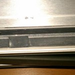
The cover slips off very nicely and holds in place when needed very firmly by a single screw - which I was surprised holds the lid in position when screwed and when unscrewed it actually moves the lid into the openable position.
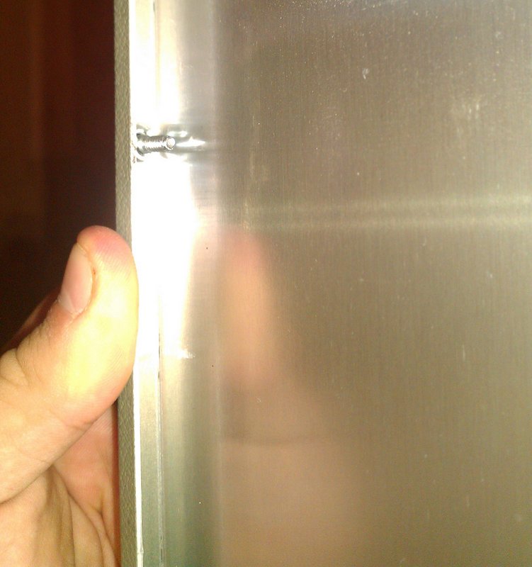
Single cover removal screw
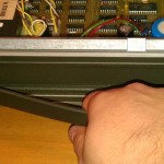
Other nice features include a HANDLE so you can easily handle and transfer your 10kg expensive bench top meter.
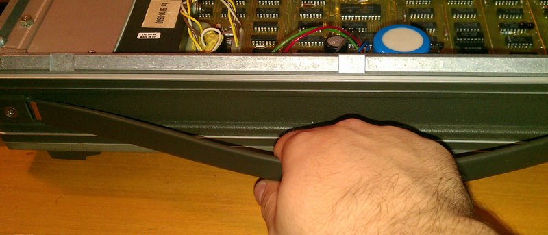
Handle usage
Oh, and here's the power switch - nicely heat shrink protected.
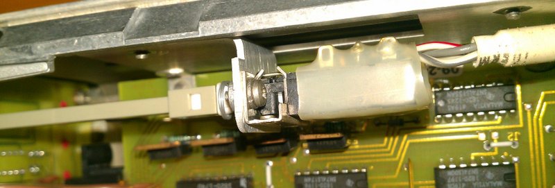
Main power switch
And that's about it. Check out the gallery below for some more detail shots of this fun device. Enjoy.
-
- The cover for the whole analog part
-
- Calibration cover removed
-
- Calibration cover removed 2
-
- More adjustment pots
-
- Even more adjustment pots – what a shocker!
-
- Cover removed
-
- Trimpots for input
-
- Input/cal cal/amp board shot 2
-
- Input/cal cal/amp board shot 3
-
- Input/cal cal/amp board shot 4
-
- Input/cal cal/amp board shot 5
-
- Input/cal cal/amp board shot 6
-
- Analog main board shot 1
-
- Analog main board shot 2
-
- Really high impedance measurement
-
- Really high impedance measurement shot 2
-
- Really high impedance measurement shot 3
-
- Attenuator and range selector
-
- Attenuator and range selector shot 2
-
- Attenuator and range selector shot 3
-
- Special, bizzare relay
-
- Special, bizzare relay
-
- Special, bizzare relay
-
- Really high impedance measurement shot 4
-
- Backside input terminals
-
- Special 10M resistor and attenuator
-
- Another attenuator shot
-
- Another another attenuator shot
-
- Calibration module input switch
-
- An isolated module
-
- The isolated module power
-
- Power supply
-
- Diodes
-
- Power supply shot 3
-
- Main module communication
-
- Main module communication
-
- Even more shielding of the analog from the digital
-
- Main clock source
-
- Main clock source
-
- High impedance connection
-
- Pull ring for a board
-
- Guard rings
-
- Local CPU and control logic
-
- Local CPU and control logic
-
- Power supply
-
- Power supply and processor
-
- Precission analog board
-
- Precission analog board
-
- Precission analog board
-
- Precission analog board
-
- Front/rear input switch
-
- Main power switch
-
- Handle
-
- Handle usage
-

- Single cover removal screw
-
- Beautiful cast case
-
- Beautiful cast case