
While going through random electronics on a local flea-market (on the Inter Stadium in Bratislava, 98+% of the items there are of no interest, but the occasional treasure can be found, beware of pickpockets) I found this little device - an old serial data generator. I bought it for the box and the switches for a nice price of 2 EUR.
NOTE: This is a teardown from which there is no coming back as I had no use for the device other than parts. Sorry.
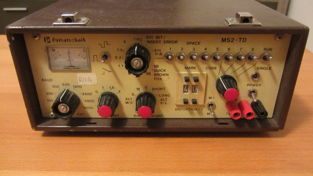
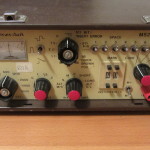
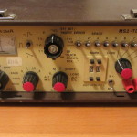
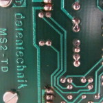
The front panel
Serial data generators are instruments for generating serial data - duh. This can be useful for analyzing a serial line parameters, seeing if your line is properly terminated, if the data is getting through well enough... basically you can generate data and put it in one end and see what goes out the other one. They are more robust and powerful (and single purpose) than your average PC port (assuming you even have one these days 😛 ).
It should be noted that the term serial data generator covers a wide range of devices - from silly old stuff like this that goes up to a whoopin' 9600 bps to devices that can do a few gigs per second and cost more than your average car (pattern generators etc.) and are obviously NOT meant for RS232.
Now onto the device: The device is housed in a neat metal box - there was a lid at some point, but I did not get it with the device. The front side is populated with all the controls
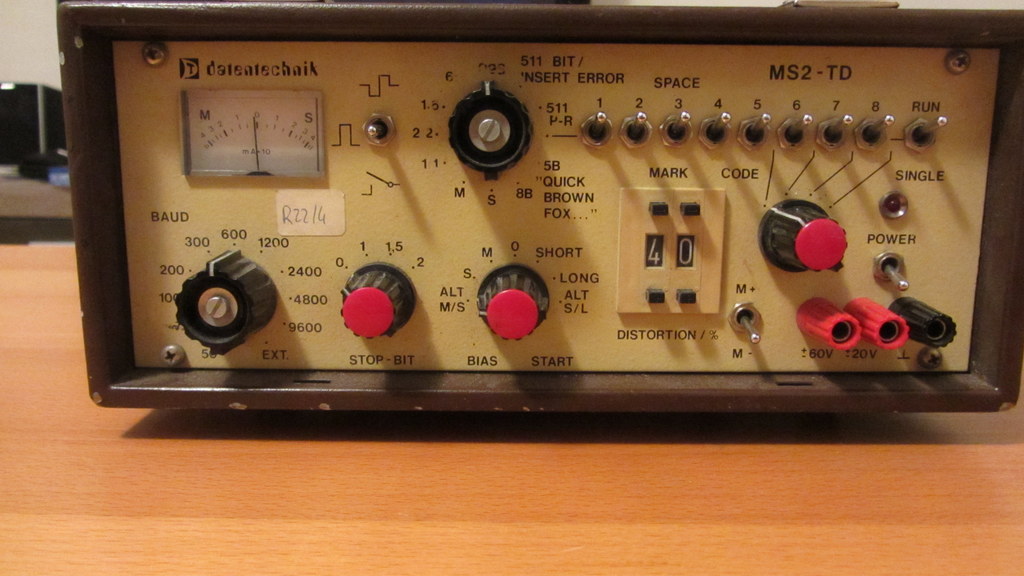
Oh my god, it's full of buttons!
Here you can set what kind of pattern you want to send, distort it, choose various parameters of the transmission, trigger it manually... also you can hook up to a few voltage values for some reason.

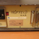
The backside
The back side has the actual outputs - it can generate pulses, or work as a switch - that's pretty useful. It's powered by 230V AC, but you can also set it to a lower voltage. It can drive the line with as much as 60V apparently - that's quite a lot. Dunno if my MAX3222 would be particularly happy about that...
And that's pretty much all there is to it on the outside - the sides are simply metal plates, the bottom has some standoffs. Nothing of interest.
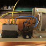
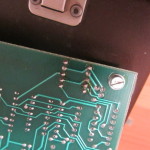
Back panel removed
After removing the back panel we get a view of the main PCB - at a quick glance you can see a lot of logic, decoupling caps and some power electronics.
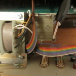
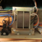
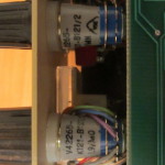
Back panel PCB
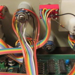
The transformer has a small PCB next to it, which is an intermediary piece between the output connectors, transformer and the min electronics.
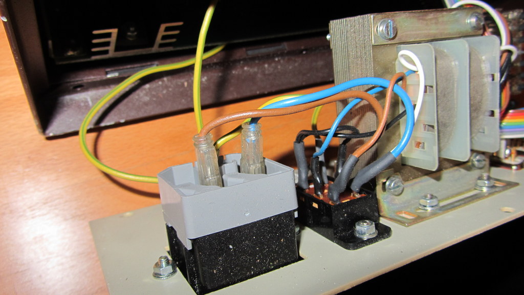
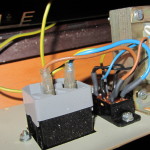
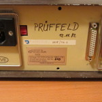
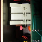
Voltage selector and mains input
Other than this there's nothing on the back panel. Removing it however is needed to enter the rest of the device - the internal assembly can't be removed without disconnecting it from the back panel electronics.
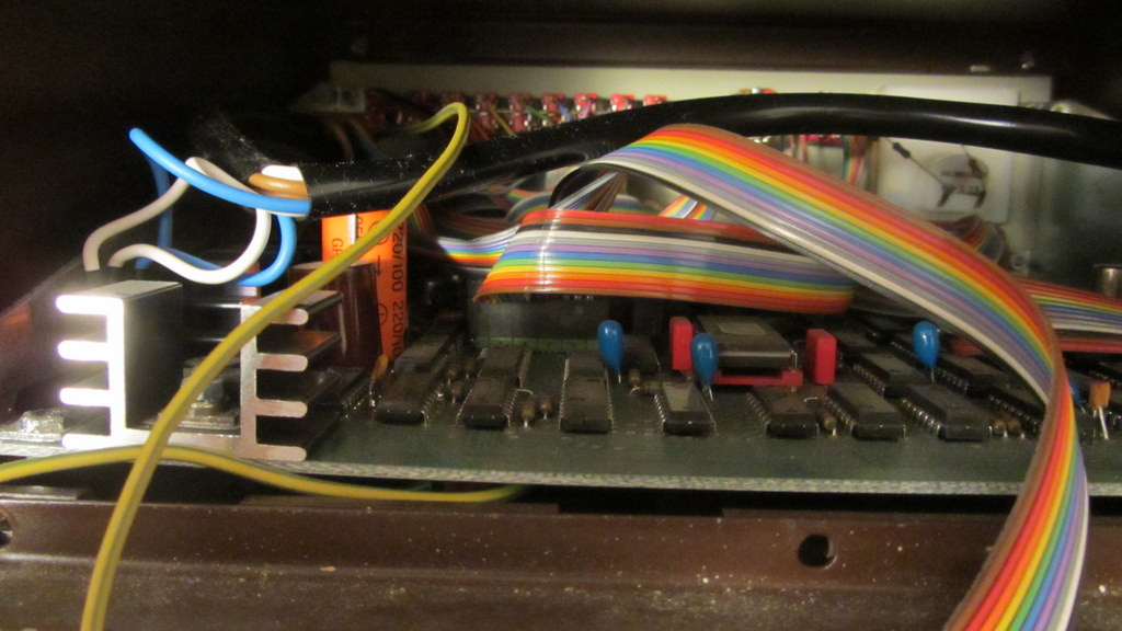
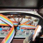
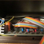
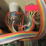
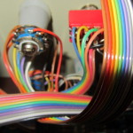
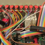
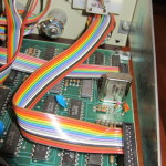
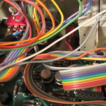
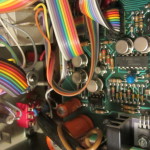
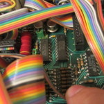
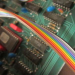
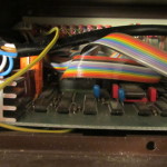
Cables! And ICs!
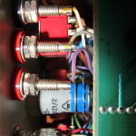
The whole inner electronics slides out on an assembly with the front panel. The front panel items (switches, buttons, meters...) are connected to the board using IDC connectors mounted onto the IDC connector on one side and soldered directly onto the control element on the other side.
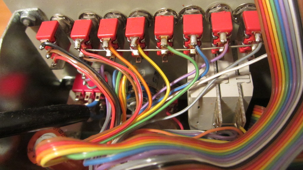
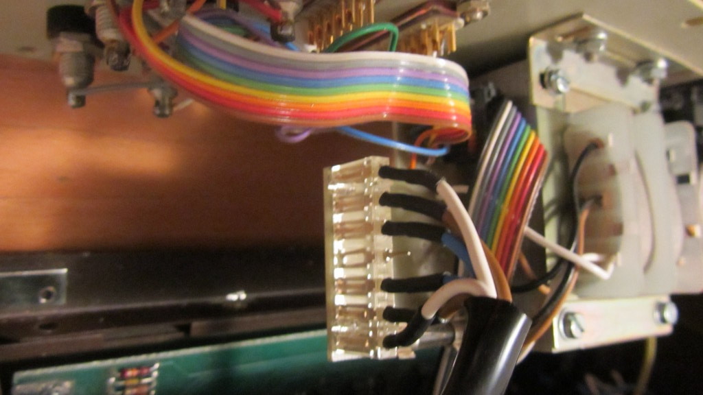
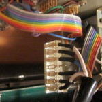
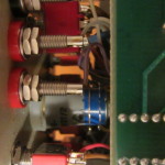
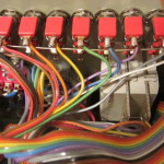
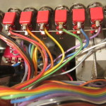
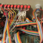
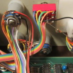
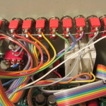
The switches
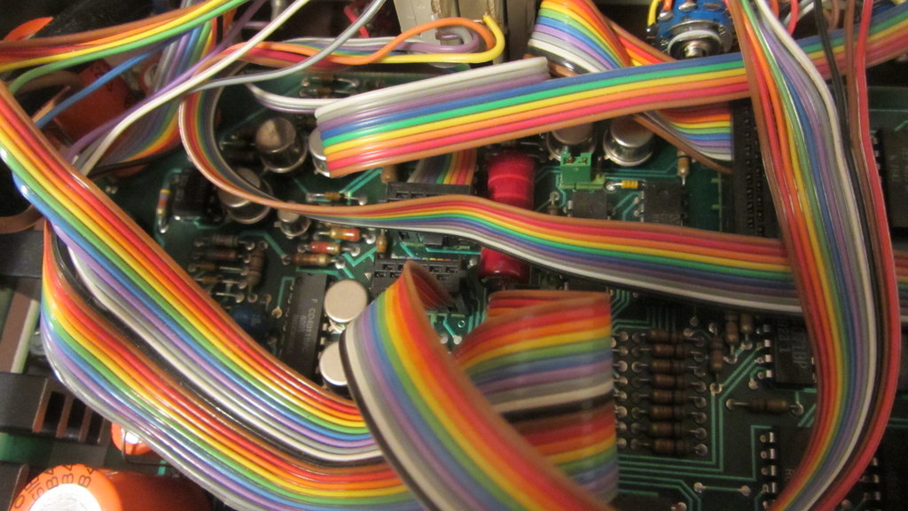
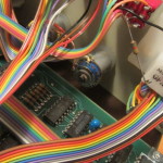
Cables
After disconnecting all of this we get into the electronics itself.
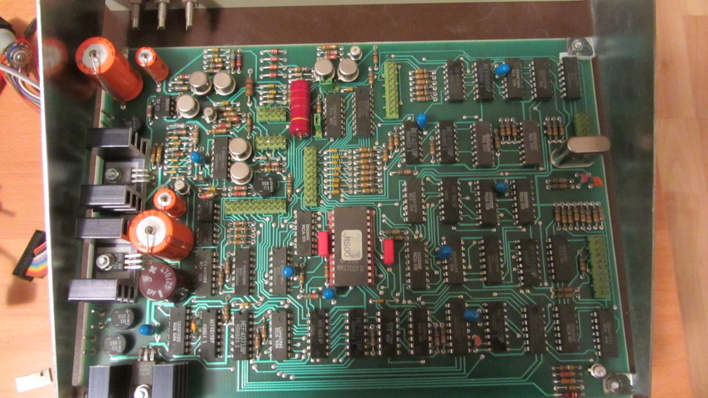
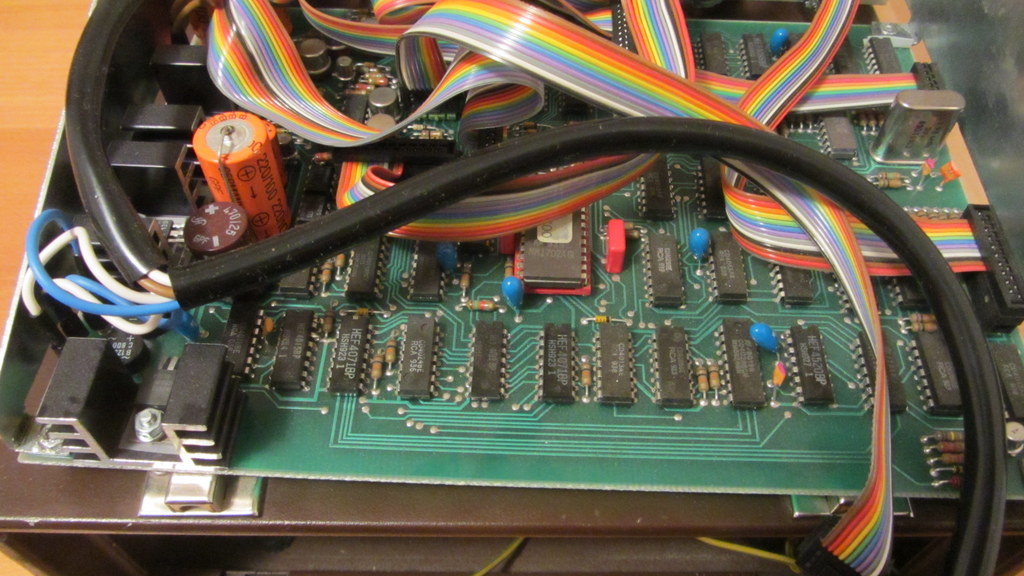
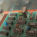
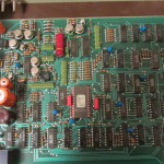
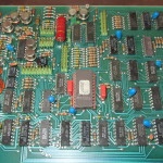
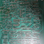
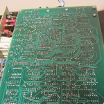
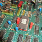
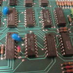
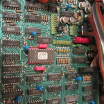
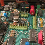
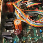
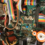
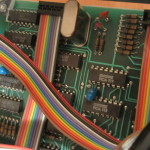
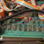
The main board
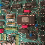
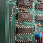
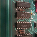
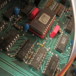
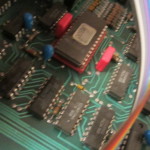
It's a two sided, mostly digital board. You can guess the individual blocks pretty easily. My guess as to the function of this is as follows - the actual byte pattern is stored in the EPROM (256 x 8) memory in the middle - this acts as the character generator and some of the logic as well. The addresses for the EPROM are generated by the counters and by the various settings.
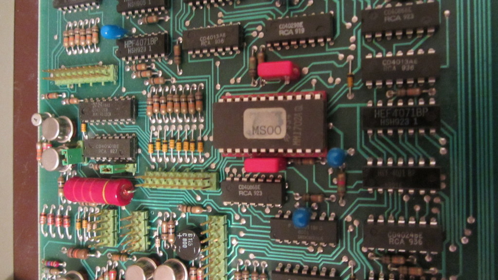
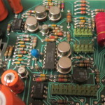
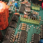
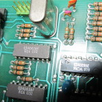
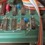
EPROM and logic
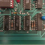
After the 'character' is generated, it passes into some selection logic which selects the bit of the byte being sent.
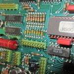
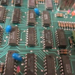
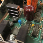
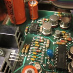
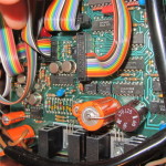
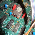
All of the timing is generated by the frequency generator and divider. The frequency is selected using the main baud rate selector, which in turn probably selects which divider output is used for the clock generation. The crystal is really beefy:
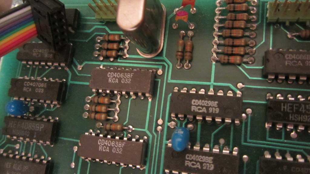
Clock generator area
Most/all of this could be easily done by your average <1 EUR microcontroller these days. It's really impressive how technology has progressed.
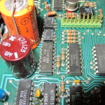
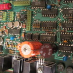
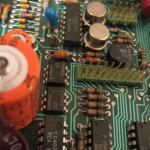
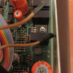
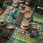
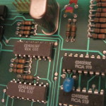
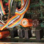
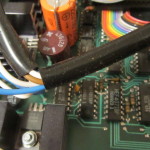
After that it's of to the analog part, which does the actual switching, conversion etc.
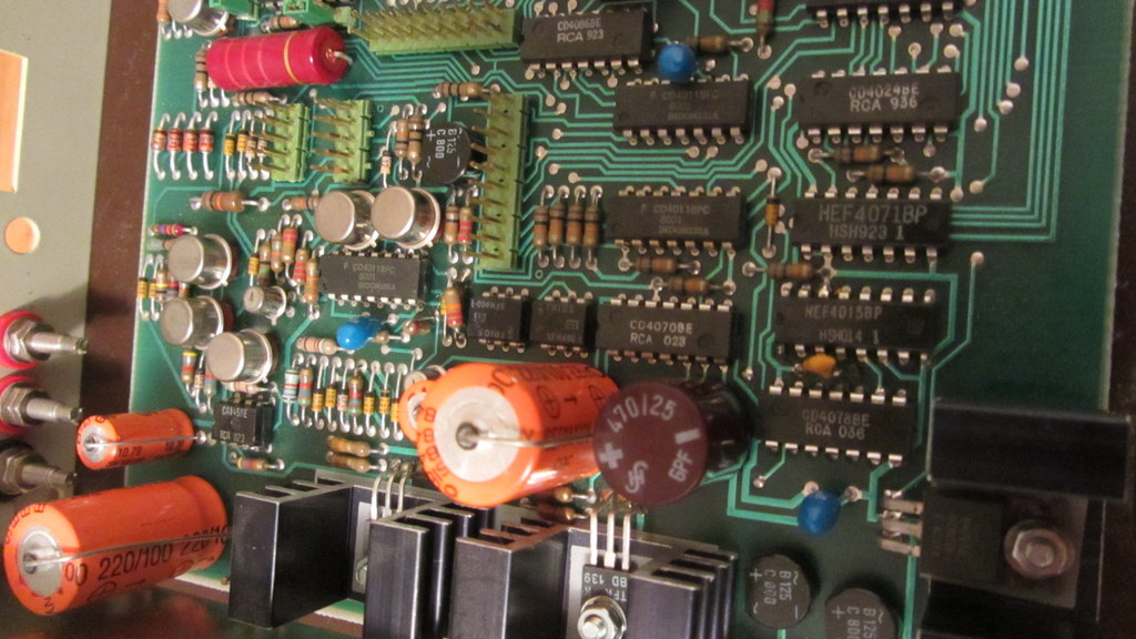
Analog and power
The power supply is also located here. It seems the analog part is optically isolated from the logic section.
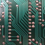
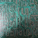
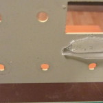
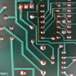
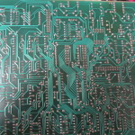
And the bottom of the board contains nothing, just connections. It was most likely wave soldered. One IC has been replaced (bottom right corner).
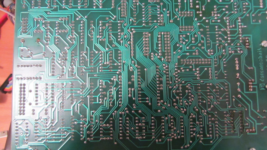
The great emptiness
And that's about it - it's an older system, which during its time probably served well. Now, I have a nice box and a few good switches/parts for an upcoming project. Well, that's the way of old tech.
Hope you enjoyed this teardown...
David out.
-
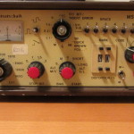
- Oh my god, it’s full of buttons!
-
- Back panel removed
-
- Voltage selector and mains input
-
- Back panel PCB
-
- The backside
-
- The front panel
-
- The great emptiness
-
- EPROM and logic
-
- Analog and power
-
- The main board
-
- Clock generator area
-
- The switches
-
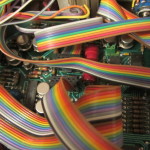
- Cables
-
- Cables! And ICs!
-
- Back panel removed