
The RETRobot is a robot I designed. You may have noticed something odd on it – it’s got a CRT tube on it. I always wanted to play around with one. I didn’t need an oscilloscope – I already have one… or two. At first I wanted to build a clock using it. But a clock is a boring device. So I built a robot. People have asked me, why a robot with a freakin’ CRT tube? If you have to ask that question, you would not understand the answer.
The robot is quite complicated – aside from the CRT and its support electronics it’s got stepper motors, which aren’t that easy to use. The whole system is linked together via a little I2C like bus.
I like to think of this project as an excursion into ancient technologies – I had to dig through various sources, ancient tech texts, manuals of old and the dreaded Electronomicon (an evil ancient book written by a brilliant and mad EE). I really enjoyed building this system.
What does it do?
Simple – you drive it remotely via BlueTooth. And display stuff on the CRT. Nothing extra really – it’s just a toy for me. Just watch this video!
Or take a look at this screenshot!

Mechanics
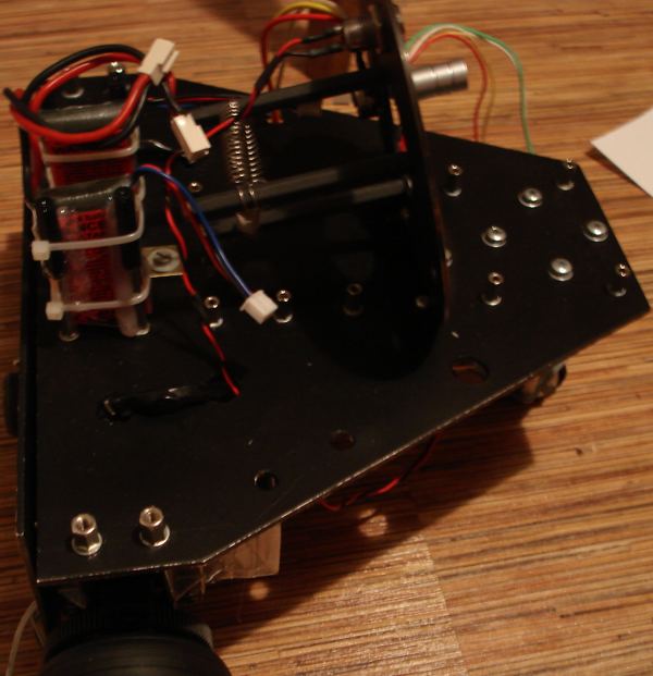
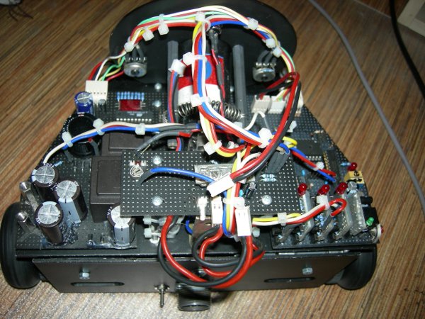
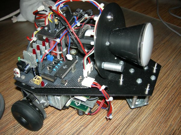
The mechanics of the robot are quite simple – basically, it’s a pretty straightforward differential wheeled robot – two active wheels with motors and one extra wheel, just passive, for balance. Everything’s on a main plate (Dural). Pictured below is the base plate with only the CRT holder assembly in place.
When you look at the robot from the front you get to see an old fashioned scope – a CRT, two knobs, all on a circular support. And all nice, simple, black, old and elegant. As for the whole design, it’s meant to point out the tube – it’s a kind of the dominant part of the design. The most visible parts of the design (the main plate) and the CRT support (and the PCBs on the top of the robot) are painted black – for aesthetic reasons.
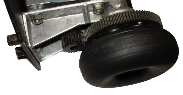
The motors are old, from communistic Germany, type ROBOTRON SPA 52/60-5683 (I acquired a datasheet for them, if you want the datasheet, please click HERE, thanks to Jorg Wunsch). They are fitted into a cast block and are geared down. The whole assembly was removed from an old German printer. Plastic wheels are connected directly onto the output shaft of the gear. The third wheel is on the front of the robot. It’s a simple wheel; it can change its orientation freely – nothing extra really. The wheel assembly is pictured above.
The primary batteries are glued to the motors using heated glue. The filament heating batteries are glued to the upper spacers – those which hold the CRT support board.
The PCBs are held up on various M3 and M4 spacers. They are isolated – the whole chassis is isolated. Cabling is held together using plastic strips.
Providing support for the CRT proved to be quite difficult – not only were magnetic fields a problem (various picture distortions), also it needed to be in a specific angled position so the user could see the picture. Oh, and it’s also very fragile, which meant no screws. In the end I chose a simple solution - the basis of the holder is a plate from an ancient hard drive. The bottom is slightly bent and has two M4 holes drilled into it – for attaching the whole plate onto the main chassis. The disk was chosen also for convenience – it’s got a nice little hole in the middle – which is almost exactly of the same diameter as the main body of the tube, just a little bigger. Three M3 holes were made around this hole – into them I placed long spacers – they support the CRTs body. Springs are used to center the CRT – at the end of the spacers, springs are stretched between them. Not too stretched, just a little. When you insert the tube, they stretch a little more to make room for the tube. At the point where the tube and the spring meet, I covered the tube with some duct tape – to increase the friction between the tube and the springs. This way, the whole setup is centered, won’t move, and just bloody works! It’s a nice and elegant solution. It's also pictured above.
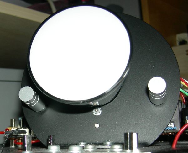
There are also two potentiometers on the CRT support plate as well as the main power key (main power isn’t routed through there, it’s infect only a little switch that goes down to the power distribution board and switches a MOSFET on and off). Oh, and a nice little LED that’s not used right now. Pictured aboce is the main plate with the CRT in place... looks like a scope, doesn't it?
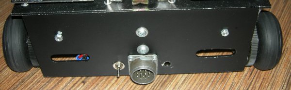
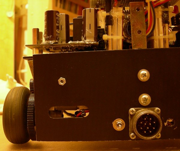
The back side of the robot is made up of a simple aluminum plate with a hole for the main power connector. I picked the connector from several options. This one is an old soviet military type connector with 11 pins, painted green. It’s so sturdy, it can hold a quite heavy plug-in module for the robot. Pictured both above and below is the back side with the lovely connector and wheels...
The electronics
The whole system consists of 4 main modules, a fair amount of cables, 2 motors, some batteries, some miscellany electronics and the CRT tube itself. There’s also the option of plug-in modules (currently there’s only one – a module for BlueTooth communication).
All the modules communicate together via an I2C like bus. The bus is also on the main connector. The main connector (it’s a lovely old sturdy soviet military 11 pin connector) is where a module can be connected. It’s got a lot of signals on it – the serial line, the bus, ground of course (signal ground and power ground are separated), +5V, +24V, and all the taps on the batteries (so the robot can be charged using this connector).
The main power is provided by 6 LiPol batteries (approx. +24V total). After that it is switched down to +5V for the control logic of the robot. The main power is directly used for the high voltage generator (two small mains transformers connected inversely, driven by an H bridge, whose output then is rectified, inverted and tripled) and the chopper drive of the stepper motors.
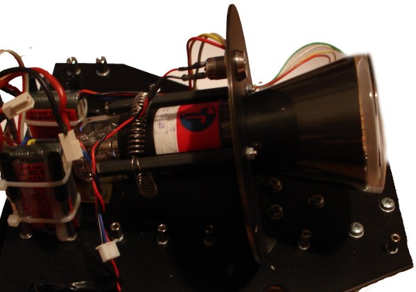
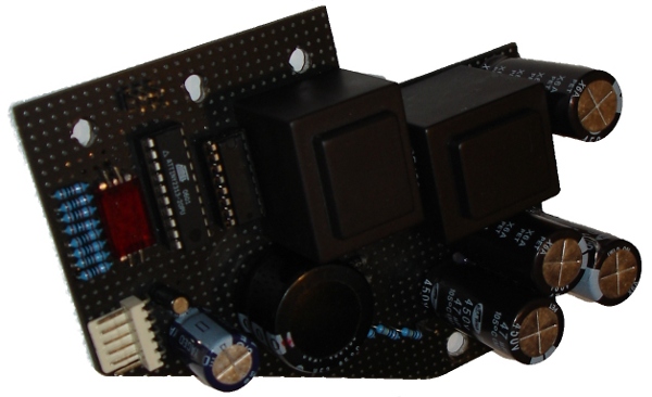
Aside from the main power there’s an additional isolated 6.3V power supply for the filament of the CRT. This is done by an extra set of LiPol batteries and a small DC/DC step down converter. Powering a cathode (both directly and indirectly heated) can be quite problematic – should the potential of the filament be, let’s say 0V and the potential of the cathode would be -600V, and then they’d start acting like a diode – which is bad. Therefore, the filament must be either floating, or connected to the same potential as the cathode. The problem was getting an isolated 6.3V/300mA on a system which has only +24V available. I chose to add another set of batteries and a DC/DC converter. I pondered about using isolated DC/DC converter, but they’re quite expensive. And effectively unobtainable here in Elbonia… er… Slovakia. In the end it was more practical just to slap on an extra set of batteries for the filament. You can see the whole top system on the picture above - on the left there's the HV PSU, on the right, there's the CRT driver, and in the middle there's the CRT support board mounted on top of the filament batteries...
Check out this video showing the problems with the CRT I've been having - the magnetic field from the transformers was affecting the CRT beam
As for the other blocks, they are described here:
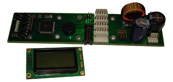
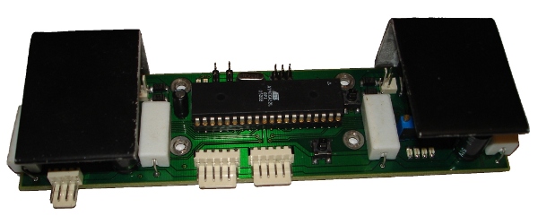
The main board – the main board is the nexus of the whole system. This module provides +5V for all the other systems, and is the master on the bus. It collects information from various systems and based on them makes decisions. It uses an ATMega128 processor, and has a small user interface on it – an LCD, a few buttons. There’s a DC/DC converter used as the main source for +5V – it is based on the LM2676 IC – just add a coil, diode, a cap here and there, and you’ve got your own instant high efficiency 3Amp DC/DC converter! Works like a charm!
The motor board – the motor board, as the name suggests, controls the motors. The motors used are bipolar stepper motors, driven via the classic duo L298 and L297, used as a chopper supply for the motors. The processor used to control the motors is an ATMega32. It is possible to set the current for the motors, and get quite a lot of info. I can also set speeds and steps for each motor individually.
The high voltage power supply and CRT support board – these two boards provide support for the CRT – it needs quite a lot of voltages ranging from -600V to +200V. The support board just provides stuff like voltage dividers (including the focus and brightness adjustment potentiometers) and connection to the CRT. There’s an ATTiny2313 processor on the board – just controlling the power supply, using PWM to make a nice sinus like signal to feed into the transformers. I had to experiment with the frequency a bit till I got the best one (it’s NOT 50Hz!!!). The transformers are driven via an H-bridge by +24V. The H-bridge used is an L293D. The support board acts more like a cabling point for various cables – pretty much the whole CRT (except the plates) is connected onto this little board. The potentiometers are on the front panel. On the whole, these boards are nothing special. Although you should have seen the face of this guy I explained the robot to, when I mentioned that there’s 800V point to point on the robot. He was kind of freaked out. I was amused.
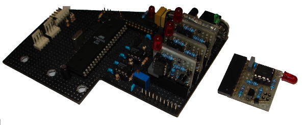
The display controller – this board contains the high voltage DAC/amplifier and the control unit – the image generator. The DAC part is a simple TLC7528 dual R2R DAC with a parallel input. Its outputs are set to 0-2V. This signal is fed to the analog part of the system, whose output is the original signal (but amplified in strength) and an opposite signal Uopposite (which is equal to 2 – Uinput). The opposite (not inverted, that would be minus Uinput, which it is not) and positive signals are needed, because the CRT is driven differentially – the voltage on one plate is the maximal voltage minus the voltage on the opposite plate. As for the high voltage part, it’s just a simple A class-like amplifier – a transistor (MPSA42) and an OPamp. This setup performs surprisingly well. At first I wanted to try the classical way – a differential amplifier with transistors. I actually tried it, but I couldn’t get it working no matter what. This setup has a 0-2V input, is powered by +/-5V and +200V, and an output of approx 0-200V. It’s really linear and performs well. There are 4 of these little boards – each one connects to one plate.
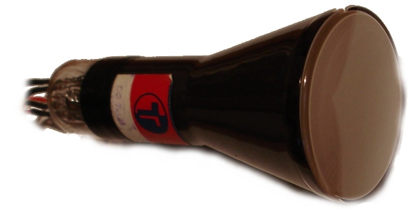
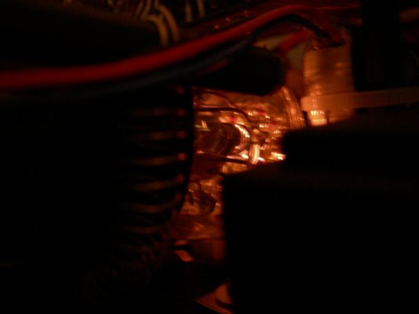
The CRT tube itself is a Tungsram DG7-123. It’s an old CRT, meant primarily for scopes. It’s got an indirectly heated cathode, all plates separated, and a lot of nice features. It’s also quite sensitive. If you’re familiar with the Tesla 7QR20 you might recognize this as the more advanced version. Physically they look identical, but the Tesla 7QR20 had a directly heated cathode, two plates connected together with the anode, and something else bad. I got it on an electronics flea market in Bratislava I visit often (contact me for information on it). Pictured above is the tube itself, pictured below is the beatiful, glowing heart of the tube... nothing quite like it in the world, is there?
(not pictured: the many months of work and tons of love it took)
Software/firmware
The firmware was written in C for AVR processors, the software for the PC was quickly hacked together in C# under the .NET platform. The most complicated part of the firmware was the display driver – basically I had to minimize the delays so there wouldn’t be flickering and the characters would be displayed nicely. The true horror came with making the font. If someone told you, that making approx. 100+ vector characters by hand was awful, he’d be making an understatement. The horror… the horror…
Fortunately, I quickly hacked together a little PC tool to help me in this horrenderous task...
Conclusion
During this project I learned quite a lot about old technologies, explored new ones and understood them better than before. Also, I had a great time building this. And I also learned that to make a robot you need:
- Resources
- Knowledge
- Love
That is all for now, if you have any questions, feel free to contact me, write something into my guestbook or something else... preferably without smoke signals. Enjoy the last video:


2 Responses to The RETRobot – the first robot with a CRT tube