
The GPIO (General Purpose Input Output) pins are the pins of a microcontroller (or other device) that can connect the device to the rest of the world, without having a particular dedicated function. In contrast to pins dedicated to a special function (JTAG/other debug, oscillator, power, reset...), these pins have either no specific dedicated role, or can be used for a specific role (such as an USART Rx/Tx) as well as a GPIO.
The pins of a microcontroller can be used in many different ways. Depending on the particular device you can set them to:
- Digital input, with or without pull-up/pull down resistors
- Digital output push-pull
- Digital output open collector/emmitor (or source/drain)
- Analog (ADC) input
- Analog (DAC) output
- ...
There are other fun functions that they may serve and combinations of functions.
For a project I needed to a resistive sensor connected as a resistive divider with a fixed value resistor. To save power when it was not in use, it was preferable to power it down when not in use (most of the time). The solution is simple - connect the top of the resistive divider to a GPIO, set it to a push/pull output, the bottom of the resistive divider will be connected to the ground. The center of the resistive divider should be connected to another GPIO.
This would work great, unfortunately it's not that simple - the GPIO is not an ideal push/pull source. The internal drive circuitry has some resistance - depending on the IC it can be up to a few hundred Ohms. What's worse, it's generally not a datasheet value (as such they can vary widely from piece to piece) and may change depending on the conditions (temperature, power supply voltage...). Essentially, it's mostly the resistance of the output transistors. A voltage drop vs. sourced/sinked current can be present in a datasheet, but with quite a lot of tolerance, as such it can't be relied upon for the more precise measurements.
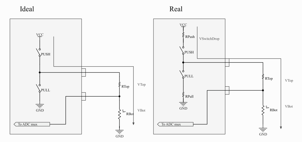
Schematic for an ideal drive vs. real
As shown above, in the ideal situation there is no influence on the measured voltage (VBot) from the internal drive circuitry - the voltage measured against ground would be:V_{Bot}=V_{CC} . \frac{R_{Bot}}{R_{Bot} + R_{Top}}. But in reality, the voltage on the bottom resistor would be V_{Bot}=V_{CC} . \frac{R_{Bot}}{R_{Bot} + R_{Top} + R_{Push}}, where RPush is the unknown resistance of the ICs internal circuitry.
I actually did a quick measurement of this. I hooked up a load onto a GPIO pin of an ATMega32L, measured and measured the load voltage and current.
The VCC was +3.29V, the ambient temperature was 20-ish °C.
The source mode (the pin was set to output a logic high):
| Current [mA] | Voltage [V] | Voltage drop [V] | Internal resistance [Ohm] |
|---|---|---|---|
| 0 | 3.289 | 0.002 | N/A |
| 3 | 3.2 | 0.091 | 30.3 |
| 6.2 | 3.1 | 0.191 | 30.8 |
| 9.3 | 3.0 | 0.291 | 31.3 |
| 12 | 2.9 | 0.391 | 32.6 |
| 14.9 | 2.8 | 0.491 | 33.0 |
| 17.5 | 2.7 | 0.591 | 33.7 |
| 19.8 | 2.6 | 0.691 | 34.9 |
The sink mode (the pin was set to output a logic low):
| Current [mA] | Voltage [V] | Internal resistance [Ohm] |
|---|---|---|
| 0 | 0 | N/A |
| 3.7 | 0.1 | 27.0 |
| 7.4 | 0.2 | 27.0 |
| 10.8 | 0.3 | 27.7 |
| 14.2 | 0.4 | 28.2 |
| 17.5 | 0.5 | 28.6 |
| 20.5 | 0.6 | 29.3 |
A quick plot of this shows quite a large voltage drop on the internal circuitry of the ATMega32 when ~10mA are drawn. A ~0.2V drop at 10mA is significant enough to cause a significant error when measuring a sensor value. Assuming VCC is used as the reference voltage, and the ADC is a 10 bit device (as the ATMega32 has) this could translate into up to 60 ADC units of error. Which is a pretty large amount.
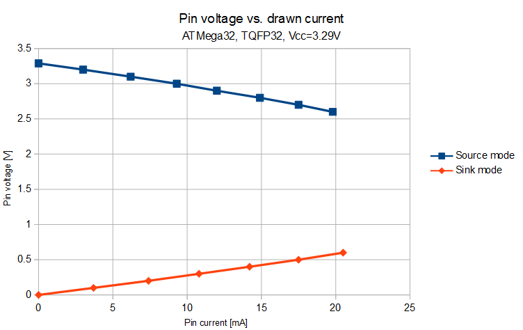
Voltage vs. sinked/sourced current on ATMega32 pin at ~20°C, +3.3V VCC
Within the measured area the resistance of the source driver (high) is around 32 Ohms, the sink driver (low) is around 28 Ohms. These values can vary between devices and change with temperature, so they can't be easily and precisely compensated against.
Essentially instead of a resistive divider that has one end tied to VCC (which can be used as the reference voltage for the ADC) you get a resistive divider that is in series with an unknown resistor, which can cause a significant error.
This can be ignored when the sensor and resistive divider are of a very high impedance or little accuracy is required. However, for lower values this can present a problem large enough to merit notice.
Solution? Measure the output!
The compensation is simple. Fortunately it's possible to actually use the GPIOs as an output and measure it at the same time. This should be possible for other architectures as well, but I only tested it for an Atmel (now Microchip 🙁 ) AVR.
This can obviously only be done with GPIOs that can be internally connected to the ADC MUX. For an ATMega32 this means every pin of PORTA. There is an internal connection to the ADC, which is independent from the I/O setting of the pin.
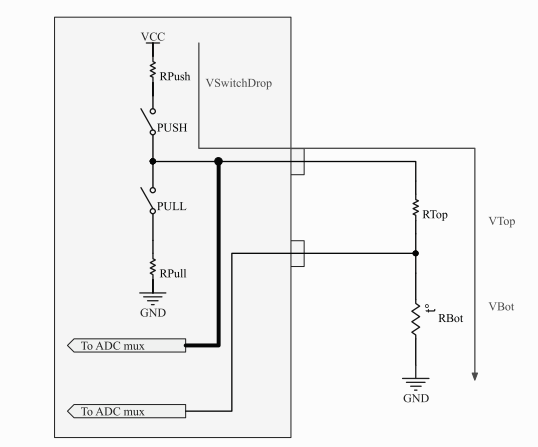
Real push pull circuitry, measured output
There is no special setting needed to do this - just set the appropriate bits in the port registers (DDRx, PORTx) to their desired states. Then switch the mux for the ADC to measure the output pin, start the ADC, wait, set the mux for the ADC to measure the input pin, start the ADC, wait and you are done. You can then power off the sensor (by setting the appropriate bit of PORTx to 0).
Most of the time in this kind of setup you are not interested in the actual voltage on the resistor, but rather the ratio between the top (let's call it the reference resistor) and the bottom resistor. The reference resistor will generally be known and the bottom resistor was in my case a thermistor. From the ratio of these resistors you can determine the resistance of the measured resistor and convert that into the measured physical quantity (temperature).
Assuming that the ADC reading from the excitation pin is N_{EXCI} and the ADC reading from the resistive divider center is R_{CENT}, then the ratio of the resistors (RTop to RBot) value of the measured resistor is:
R_{Bot}=\frac{R_{Top}N_{CENT}}{N_{EXC}-N_{CENT}}
R_{Bot}=\frac{R_{Top}N_{CENT}}{N_{EXC}-N_{CENT}}
Conclusion
Using this simple math and turning on your sensors only when you need them you can have a precise, yet low power sensor when you need it.
It takes just a little more resources (floating point math can get nasty on 8 bits), but it's worth it - in particular when you have to deal with a low resistance device, such as a thermistor or a potentiometer and you want to get the most of it.
The method can obviously be used whether you are connecting the top of the resistor to VCC or GND. Or even both, if current polarity change is desirable. Obviously, the math then needs to be adjusted a bit.
Enjoy.